Description
			
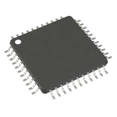
Atmel’s AT91SAM7S is a series of low pincount Flash microcontrollers based on the 32-bit ARM RISC processor. It features a high-speed Flash and an SRAM, a large set of peripherals, including a USB 2.0 device (except for the AT91SAM7S32 and AT91SAM7S16), and a complete set of system functions minimizing the number of external components. The device is an ideal migration path for 8-bit microcontroller users looking for additional performance and extended memory.			


Features
			
• Incorporates the ARM7TDMI® ARM® Thumb® Processor
			
– High-performance 32-bit RISC Architecture
			
– High-density 16-bit Instruction Set
			
– Leader in MIPS/Watt
			
– EmbeddedICE™ In-circuit Emulation, Debug Communication Channel Support
			
• Internal High-speed Flash
			
– 512 Kbytes (AT91SAM7S512) Organized in Two Contiguous Banks of 1024 Pages of 256 Bytes (Dual Plane)
			
– 256 Kbytes (AT91SAM7S256) Organized in 1024 Pages of 256 Bytes (Single Plane)
			
– 128 Kbytes (AT91SAM7S128) Organized in 512 Pages of 256 Bytes (Single Plane)
			
– 64 Kbytes (AT91SAM7S64) Organized in 512 Pages of 128 Bytes (Single Plane)
			
– 32 Kbytes (AT91SAM7S321/32) Organized in 256 Pages of 128 Bytes (Single Plane)
			
– 16 Kbytes (AT91SAM7S161/16 Organized in 256 Pages of 64 Bytes (Single Plane)
			
– Single Cycle Access at Up to 30 MHz in Worst Case Conditions
			
– Prefetch Buffer Optimizing Thumb Instruction Execution at Maximum Speed
			
– Page Programming Time: 6 ms, Including Page Auto-erase, Full Erase Time: 15 ms
			
– 10,000 Write Cycles, 10-year Data Retention Capability, Sector Lock Capabilities, Flash Security Bit
			
– Fast Flash Programming Interface for High Volume Production
			
• Internal High-speed SRAM, Single-cycle Access at Maximum Speed
			
– 64 Kbytes (AT91SAM7S512/256)
			
– 32 Kbytes (AT91SAM7S128)
			
– 16 Kbytes (AT91SAM7S64)
			
– 8 Kbytes (AT91SAM7S321/32)
			
– 4 Kbytes (AT91SAM7S161/16)
			
• Memory Controller (MC)
			
– Embedded Flash Controller, Abort Status and Misalignment Detection
			
• Reset Controller (RSTC)
			
– Based on Power-on Reset and Low-power Factory-calibrated Brown-out Detector
			
– Provides External Reset Signal Shaping and Reset Source Status
			
• Clock Generator (CKGR)
			
– Low-power RC Oscillator, 3 to 20 MHz On-chip Oscillator and one PLL
			
• Power Management Controller (PMC)
			
– Software Power Optimization Capabilities, Including Slow Clock Mode (Down to 500 Hz) and Idle Mode
			
– Three Programmable External Clock Signals
			
• Advanced Interrupt Controller (AIC)
			
– Individually Maskable, Eight-level Priority, Vectored Interrupt Sources
			
– Two (AT91SAM7S512/256/128/64/321/161) or One (AT91SAM7S32/16) External Interrupt Source(s) and One Fast Interrupt Source, Spurious Interrupt Protected
			
• Debug Unit (DBGU)
			
– 2-wire UART and Support for Debug Communication Channel interrupt, Programmable ICE Access Prevention
			
– Mode for General Purpose 2-wire UART Serial Communication
			
• Periodic Interval Timer (PIT)
			
– 20-bit Programmable Counter plus 12-bit Interval Counter
			
• Windowed Watchdog (WDT)
			
– 12-bit key-protected Programmable Counter
			
– Provides Reset or Interrupt Signals to the System
			
– Counter May Be Stopped While the Processor is in Debug State or in Idle Mode
			
(Continue ...)