3. Structural materials | ||
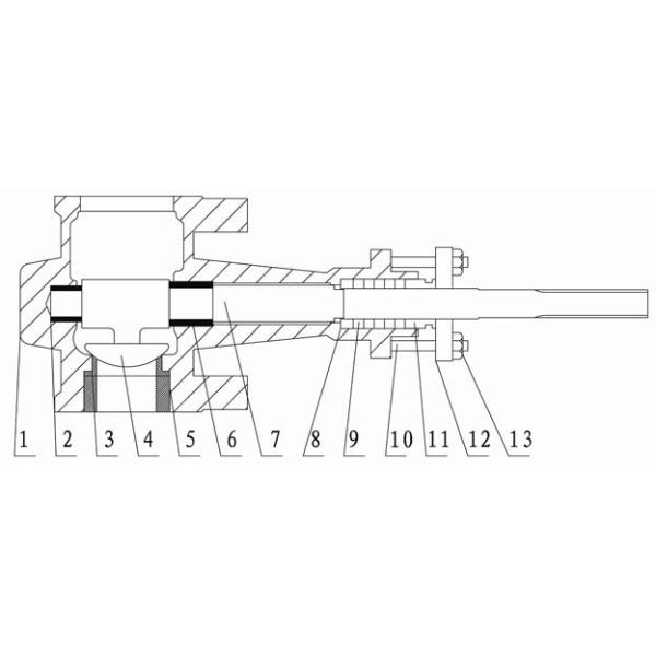
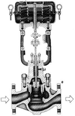
Serial Number | Name | Material |
1 | Valve Body | WCBSCS13SCS14ZG25ZGlCr18Ni9ZG0Cr18Ni12Mo2Ti |
2 | Lower Guide Bushing | 9Cr18SUS316+ST |
3 | Valve Seat | 0Cr18Ni12Mo2TiSUS316+ST |
4 | Valve Core | SUS316+ST |
5 | Gland Nut | 0Cr18Ni12Mo2TiSUS316+ST |
6 | Upper Guide Bushing | 9Cr18SUS316+ST |
7 | Valve Stem | 0Cr18Ni12Mo2TiSUS316 |
8 | Gasket | 1Cr18Ni90Cr18Ni12Mo2Ti |
9 | Packing | Polytetrafluoroethylene + asbestos graphite |
10 | Packing bolt | 1Cr18Ni9 |
11 | Packing gland | 1Cr18Ni9 |
12 | Pressure plate | ZG25ZG1Cr18Ni9 |
13 | Nut | 1Cr18Ni9 |
4. Allowable pressure difference
(1) Hard seal structure Unit: MPa | ||||||||||||||
Caliber | Cv | Air-to-open and flow-opening type | Air-to-open and flow-closing type or air-to-close and flow-opening type | |||||||||||
Air supply pressure | ||||||||||||||
0.14 | 0.18 | 0.21 | 0.25 | 0.28 | 0.32 | 0.35 | 0.39 | 0.42 | 0.46 | 0.49 | 0.53 | |||
1" | 14 5.6 | 7.0 10.2 | 7.0 10.0 | |||||||||||
" 1 1 2 | 30 12 | 4.7 9.8 | 3.0 6.3 | 5.6 10.2 | ||||||||||
2" | 50 20 | 2.5 5.2 | 1.6 3.3 | 3.5 7.0 | 4.2 7.0 | |||||||||
3" | 135 54 | 2.0 4.5 | 1.3 2.8 | 2.7 6.1 | 4.2 7.0 | |||||||||
4" | 230 92 | 1.0 2.2 | 0.63 1.4 | 1.4 3.0 | 2.2 4.9 | 3.1 6.8 | 3.9 7.0 | 4.1 7.0 | ||||||
6" | 500 | 0.63 | 0.35 0.35 0.35 | 0.91 0.91 0.91 | 1.4 1.4 1.4 | 2.1 2.1 2.1 | 2.5 2.5 | 3.1 3.1 | 3.7 3.7 | 4.2 4.2 | ||||
200 | 1.4 | 0.77 0.77 0.77 | 2.0 2.0 2.0 | 3.2 3.2 3.2 | 4.4 4.4 3.5 | 5.6 5.6 | 6.8 6.8 | 7.0 7.0 | ||||||
850 | 0.32 | 0.18 0.18 0.18 | 0.42 0.42 0.42 | 0.7 0.7 0.63 | 1.0 1.0 | 1.3 1.3 | 1.5 | 1.8 | 2.1 | 2.4 | 2.5 | |||
8" | 510 | 0.49 | 0.28 0.28 0.28 | 0.7 0.7 0.7 | 1.1 1.1 1.0 | 1.5 1.5 | 2.0 2.0 | 2.4 | 2.8 | 3.2 | 3.7 | 3.9 | ||
340 | 0.77 | 0.42 0.42 0.42 | 1.1 1.1 1.0 | 1.8 1.8 1.5 | 2.5 2.5 | 3.2 3.2 | 3.9 | 4.5 | 5.2 | 5.9 | 6.3 | |||
10" | 1300 | 0.18 | 0.11 0.11 0.11 | 0.25 0.25 0.25 | 0.38 0.35 0.38 | 0.56 0.56 | 0.7 0.7 | 0.84 | 0.98 | 1.1 | 1.3 | 1.5 | ||
780 | 0.42 | 0.14 0.14 0.14 | 0.35 0.35 0.35 | 0.56 0.56 0.49 | 0.84 0.84 | 1.1 1.1 | 1.3 | 1.5 | 1.8 | 2 | 2.2 | |||
520 | 0.42 | 0.25 0.25 0.25 | 0.63 0.63 0.63 | 0.98 0.98 0.84 | 1.3 1.3 | 1.7 1.7 | 2.1 | 2.5 | 2.8 | 3.2 | 3.6 | |||
1750 | 0.11 | 0.14 0.14 0.14 | 0.21 0.21 0.621 | 0.32 0.32 | 0.39 0.39 | 0.49 0.42 | 0.56 | 0.63 | 0.7 | 0.84 | ||||
12" | 1050 | 0.14 | 0.07 0.07 0.07 | 0.21 0.21 0.21 | 0.35 0.35 0.32 | 0.49 0.49 | 0.63 0.63 | 0.7 | 0.84 | 0.98 | 1.1 | 1.3 | ||
700 | 0.25 | 0.14 0.14 0.14 | 0.35 0.35 0.35 | 0.56 0.56 0.49 | 0.77 0.77 | 0.98 0.98 | 1.3 | 1.5 | 1.7 | 1.9 | 2.1 |
(2) Soft seal structure Unit: MPa | ||||||||||||||
Caliber | Cv | Air-to-open and flow-opening type | Air-to-open and flow-closing type or air-to-close and flow-opening type | |||||||||||
Air supply pressure | ||||||||||||||
0.14 | 0.18 | 0.21 | 0.25 | 0.28 | 0.32 | 0.35 | 0.39 | 0.42 | 0.46 | 0.49 | 0.53 | |||
1" | 14 5.6 | 5.6 7.0 | 5.6 7.0 | |||||||||||
" 1 1 2 | 30 12 | 3.5 7.0 | 1.6 3.7 | 4.9 7.0 | ||||||||||
2" | 50 20 | 1.8 3.7 | 0.7 1.6 | 2.6 5.3 | 4.2 7.0 | |||||||||
3" | 135 54 | 1.4 3.4 | 0.62 1.6 | 2.1 4.8 | 3.5 5.6 | |||||||||
4" | 230 92 | 0.7 1.6 | 0.25 0.7 | 1.1 2.3 | 1.8 4.0 | 2.6 5.6 | 3.4 5.6 | 3.5 5.6 | ||||||
6" | 500 | 0.42 | 0.14 0.14 0.14 | 0.63 0.63 0.63 | 1.2 1.2 1.2 | 1.7 1.7 1.7 | 2.2 2.2 2.5 | 2.7 2.7 | 3.2 3.2 | 3.5 3.5 | ||||
200 | 1.1 | 0.42 0.42 0.42 | 1.5 1.5 1.5 | 2.7 2.7 2.7 | 3.7 3.7 3.7 | 4.8 4.8 | 5.6 5.6 | |||||||
850 | 0.14 | 0.28 0.28 0.28 | 0.52 0.52 0.52 | 0.77 0.77 0.63 | 1.1 1.1 | 1.3 1.3 | 1.5 | 1.8 | 2.1 | |||||
8" | 510 | 0.28 | 0.07 0.07 0.07 | 0.46 0.46 0.46 | 0.84 0.84 0.84 | 1.2 1.2 0.96 | 1.6 1.6 | 2.0 2.0 | 2.4 | 2.8 | 3.2 | |||
340 | 0.49 | 0.14 0.14 0.14 | 0.77 0.77 0.77 | 1.4 1.4 1.4 | 2.0 2.0 1.5 | 2.6 2.6 | 3.2 3.2 | 3.8 | 4.4 | 4.9 | ||||
10" | 1300 | 0.11 0.11 0.11 | 0.25 0.25 0.25 | 0.38 0.38 0.35 | 0.53 0.53 | 0.67 0.67 | 0.77 0.70 | 0.91 | 1.1 | 1.2 | ||||
780 | 1.1 | 0.21 0.21 0.21 | 0.42 0.42 0.42 | 0.63 0.63 0.63 | 0.84 0.84 | 1.1 1.1 | 1.3 | 1.5 | 1.7 | 1.9 | ||||
520 | 0.21 | 0.35 0.35 0.35 | 0.7 0.7 0.7 | 1.1 1.1 0.84 | 1.3 1.3 | 1.7 1.7 | 2 | 2.3 | 2.7 | 3 | ||||
1750 | 0.04 0.04 0.04 | 0.11 0.11 0.11 | 0.18 0.18 0.18 | 0.28 0.28 0.21 | 0.35 0.35 | 0.42 0.42 | 0.49 | 0.6 | 0.67 | |||||
12" | 1050 | 0.07 0.07 0.07 | 0.21 0.21 0.21 | 0.32 0.32 0.32 | 0.46 0.46 | 0.56 0.56 | 0.7 | 0.77 | 0.91 | 1.1 | ||||
700 | 0.07 | 0.18 0.18 0.18 | 0.35 0.35 0.35 | 0.56 0.56 0.56 | 0.77 0.77 | 0.91 0.91 | 1.1 0.90 | 1.3 | 1.5 | 1.8 | ||||
Accessories
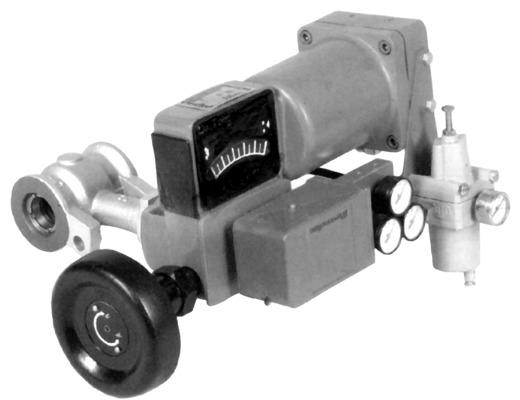
Since the flow characteristic of the FR series pneumatic eccentric rotary control valve is approximately linear, a valve positioner (including an air filter pressure reducer) must be equipped in occasions where control accuracy is required. In addition, auxiliary components such as electro-pneumatic converters, position retaining valves, safety valves, travel switches, and solenoid valves can also be equipped according to process requirements.