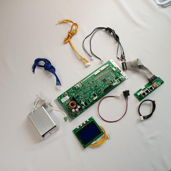
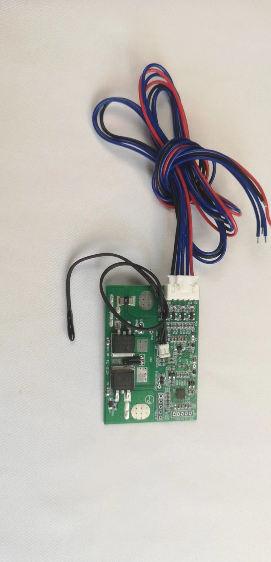
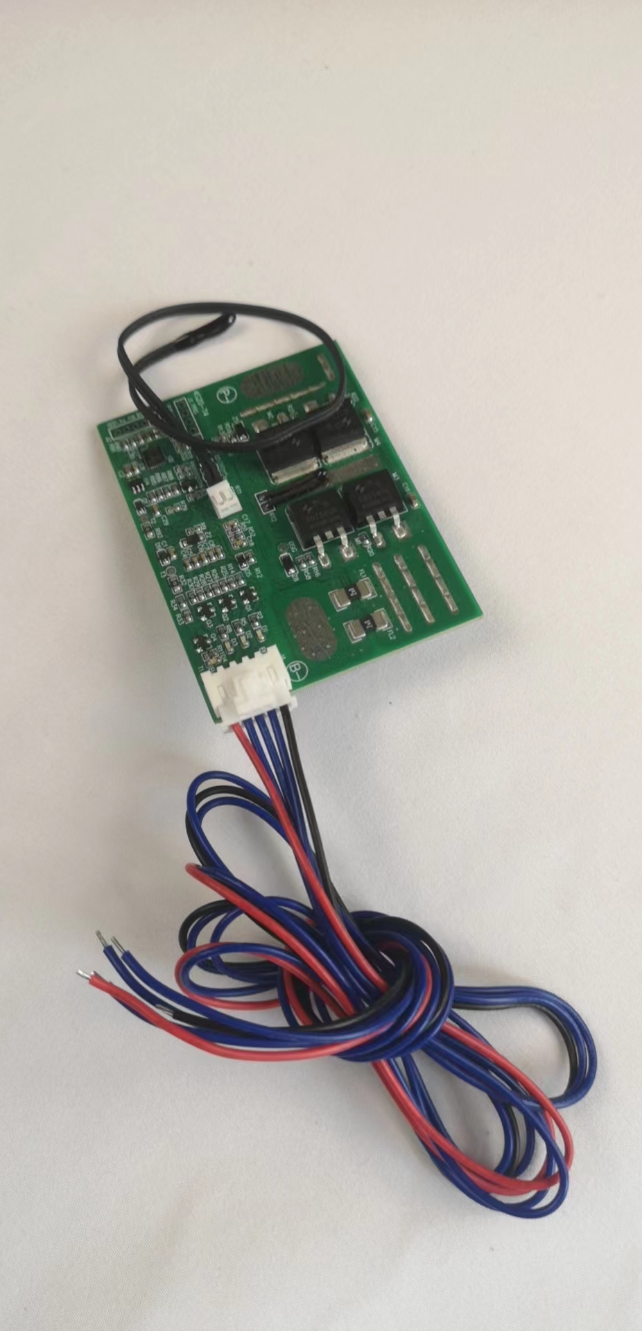
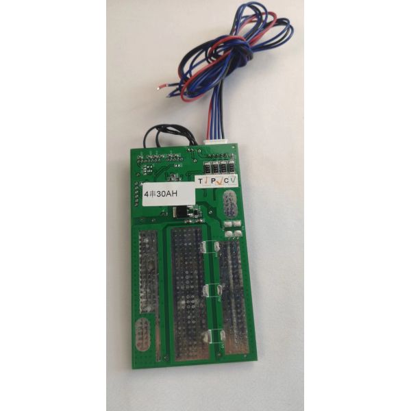
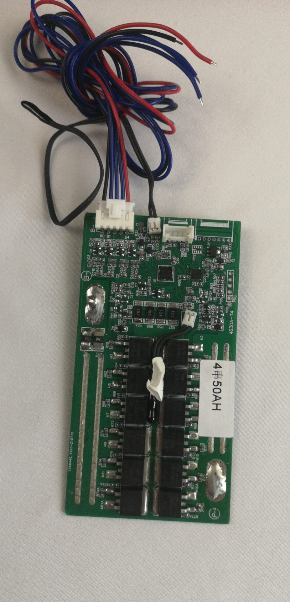
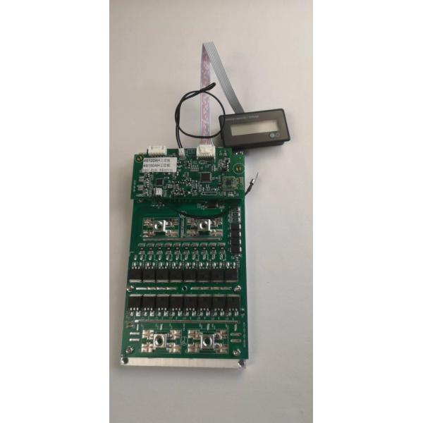
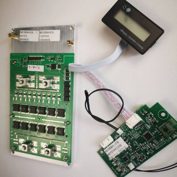
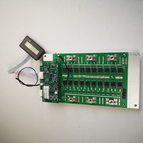
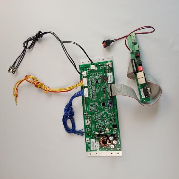
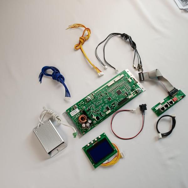
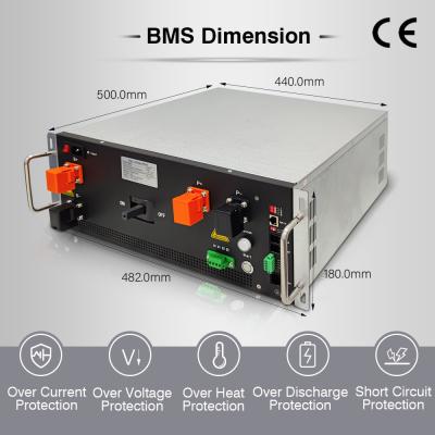
16S 51.2V 100A Master BMS Lifepo4 With RS485 Or CAN For ESS UPS

Basic configuration and performance:
| Basic parameters | |
| Cell type | lithium iron phosphate |
| Rated Capacity | 100AH |
| Number of battery strings | 16S |
| Rated working current | 100A |
| Maximum current limit charging current | 10A(battery)(40V) |
| Maximum charging voltage | 57V |
| Balance | |
| Balance type | Passive balancing |
| Balance current | 150mA±10mA (Single cell 3.40V) |
| Temperature sampling | |
| Battery temperature Sensor | 4 |
| PCB temperature Sensor | 1 |
| Environmental temperature sensor | 1 |
| Sampling accuracy | ±2℃ |
| Voltage sampling | |
| Sampling accuracy | Single cell ±15mV@25℃ |
| Current sampling | |
| Sampling range | 120A/-130A(charge/-discharge) |
| Sampling accuracy | FSC±5% |
| SOC | |
| Tolerance | ≤5% |
| Power consumption | |
| Sleep mode | ≦ 400uA |
| Working mode | ≦ 16 mA/28 MA(Current-limited charging) |
| Communication interface/protocol | |
| RS485/custom protocol | 1 way, battery master- slave parallel internal communication |
| RS485 | 1 way for communication with energy storage inverter |
| CAN(optional) | 1 way for communication with energy storage inverter |
| Other options | |
| Data collection box (optional) | No(default) |
| Reverse polarity protection (optional) | No(default value) |
| Parallel requirements (optional) | Needed (default value), No need |
| Heating film (optional) | No need (default value) |
| BMS status output | LED (default value) |
| Gyro anti-theft | No (default value) |
Communication Port:
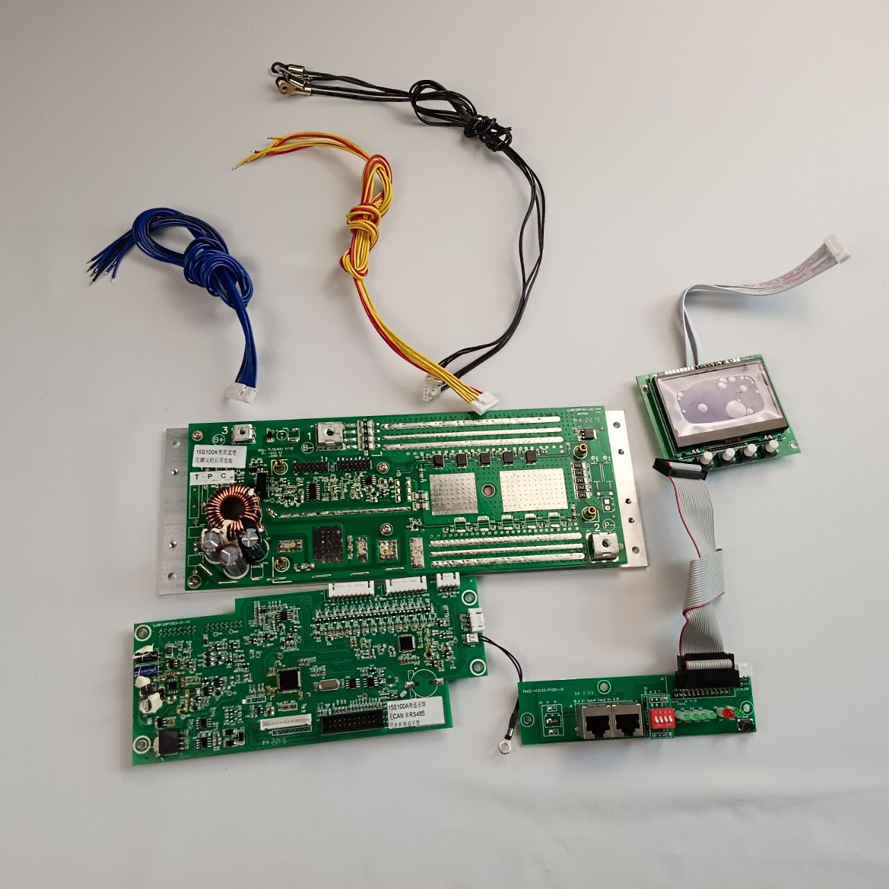
The communication circuit of this system is two RS485 and one CAN communication interface;
One RS485 communicates with the host computer or with the energy storage inverter, the baud rate is set to 9600 by default;
One RS485 is used for internal communication when batteries are connected in parallel;
The RS485 interface uses two RJ45 sockets. The socket pins are defined in the following table:
| Signal definition | RJ45*2 (two with the same effect) |
| RS485 A+(T/R+) | PIN-2,-7 |
| RS485 B-(T/R-) | PIN-1,-8 |
| Isolated power supply V- | PIN-3,-6 |
| No definition yet (reserved) | PIN-4,-5 |
BMS Protection Parameters (@25℃, except temperature protection):
| category | Item | Protection value | Delay | Releasing conditions (the following restoration conditions 1 and 2 are the OR relationship) | Parameters can be set |
| Charge
| Single-cell overvoltage warning | 3.70V |
|
| yes |
| Single cell overvoltag e protection | 3.80V | 1-2S | 1. Discharge current>1.0A or
| yes | |
| Overall overvoltag e warning | 59.2V |
|
| yes | |
| Overall overcharge protection | 60.0V | 1-2S | 1. Discharge current>1.0A or | yes | |
| charge protection | >102A | The 20S | Switch to current-
| yes | |
| Charge protection | ≥ 112A | 2-3S | yes | ||
| Discharge
| Single-cell | 2.8V |
|
| yes |
| Single | 2.5V | 1-2S | 1. Charging current>1.0A or | yes | |
| Overall | 45.0V |
|
| yes | |
| Overall discharge | 43.2V | 1-2S | 1. Charging current>1.0A 2. The voltage of the whole group has risen by 48.0V and the cell voltage is higher than 3.1V | yes | |
| Discharge | 102A |
|
| yes | |
| Discharge | >102A and <122A | 30S | 1. Charging 2. The protection will be automatically released after 60 seconds | yes | |
| Discharge | ≥ 122A | 2-3S | 1. Charging current>1.0A | yes | |
| Short | Short |
| 1. Charging current>1.0A or | yes | |
| Cell
| Charging high and low temperature warning | ≦ -3℃, ≥ 65℃ |
|
| yes |
| Charging | ≦ -5℃, ≥70℃ |
| 1. When charging, the temperature is higher than 0℃ and lower than 60℃ to recover | yes | |
| Discharge | ≦ -20℃, ≥70℃ |
|
| yes | |
| Discharge | ≦ -25℃, ≥75℃ |
| 1. The temperature is higher than -15° C and lower than 65°C during discharge to recover | yes | |
| PCB
| PCB high | ≥90℃ |
|
| yes |
| PCB high | ≥95℃ |
| <80℃ | yes | |
| environm ent temperature
| Ambient | ≦ -15℃, ≥ 65℃ |
|
| No |
| Ambient | ≦ -20℃, ≥70℃ |
| The temperature is higher than -10℃ and lower than 60℃ to recover | No | |
| SOC | SOC low | ≦ 5% |
| >5% | No |
| 4S BMS | |||||
![]() | ![]() | ![]() | ![]() | ![]() | ![]() ![]() |
| 4S 10A | 4S 20A | 4S 30A | 4S 50A | 4S 100A | 4S 150A/200A |
| 8S BMS | |||||
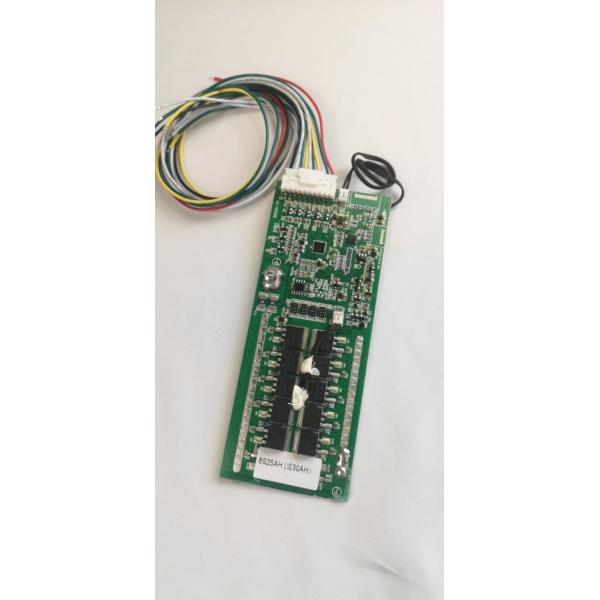
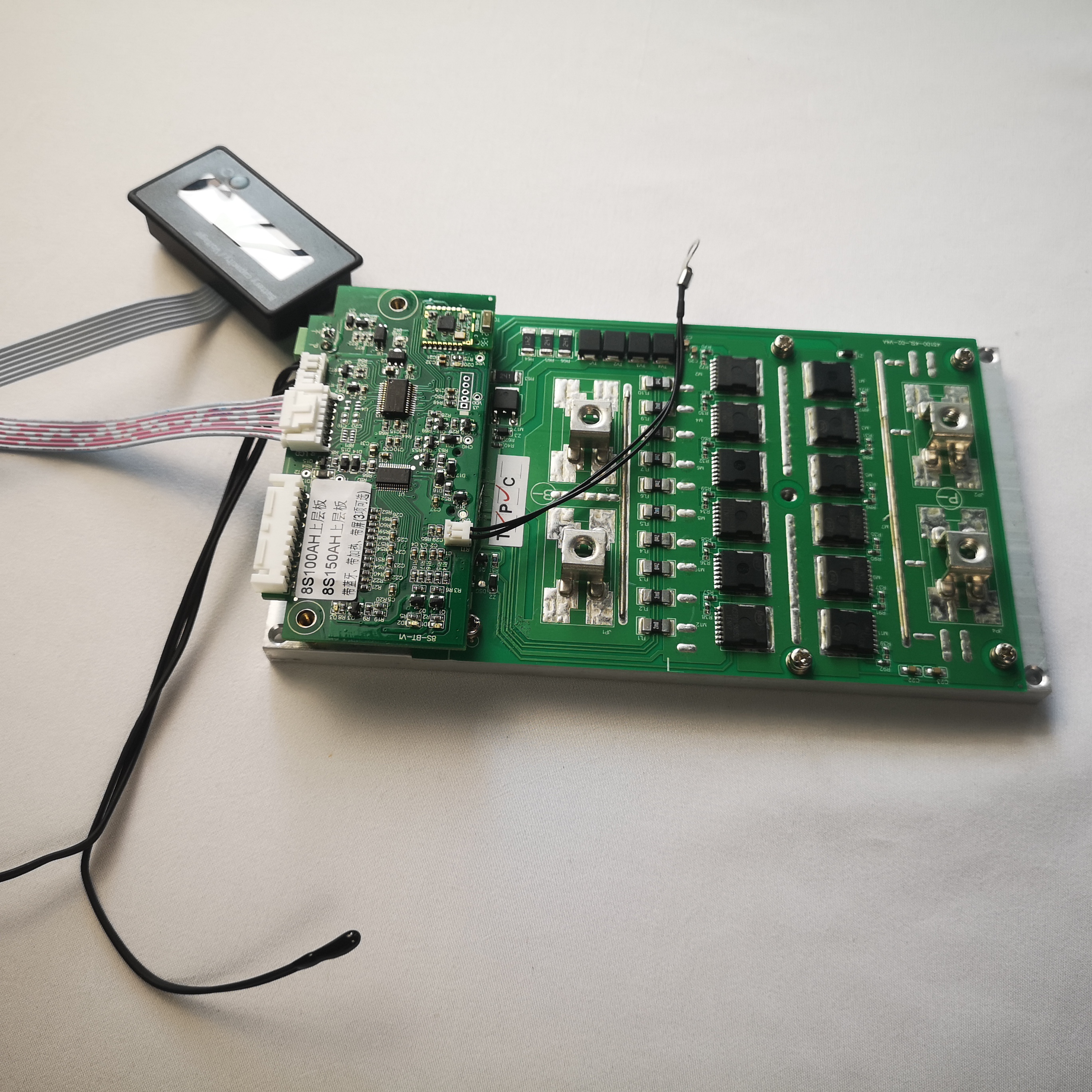
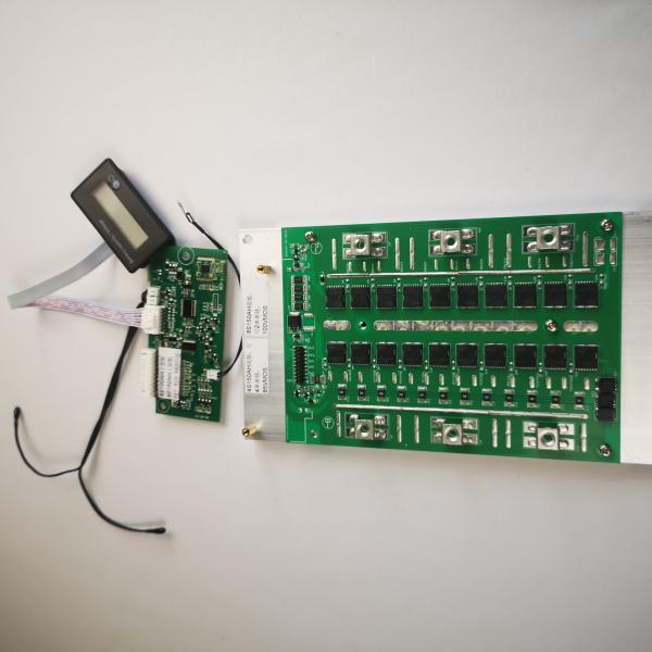
![]() | ![]() | ![]() | |||
| 8S 25A | 8S 100A | 8S 150A | |||
| 15S BMS | |||||
![]() | ![]() | ||||
| 15S 100A With LCD Display | 15S 100A With Gyroscope | ||||
| 16S BMS | |||||
![]() | |||||
Contact Us:
GCE is a professional high voltage life4po BMS muanfacturer,
Made BMS voltage from 48V to 1000V with master and slave three-level structure solution,
12S-24S lithium battery BMS, battery storage BMS for energy storage system,UPS,ESS,off-gird/Hybrid solar system,Grid-Tie solar system solution proivder.
4S to 24s low voltage software BMS has a wide range of uses, rich product interfaces, strong scalability and secondary development compatibility;
30s to 75s BMS adopts master-slave integrated design and relay solution to meet the lithium battery demand of multiple strings of small capacity batteries.
Greatly reduce the use cost of users; 60s-270s adopts master-slave three-level architecture, which can meet the series and parallel requirements of high-capacity single lithium batteries within 1000V.
By mastering the core technology of BMS and inventing on this basis, our company has developed a variety of lithium battery peripherals to meet the high-quality needs of the market.

Application:
Battery Energy Storage System(BESS)
Off-grid energy storage
Data Center
Grid frequency modulation energy storage
Track power / traction
LFP UPS power supply