With societal advancement, demands for electrical safety and reliability have grown significantly. High-voltage circuit breakers serve dual functions of control and protection in power systems, and their performance directly impacts the safe operation of these systems. Mechanical characteristic parameters are critical indicators for evaluating breaker performance. The GKC-G3 High-Voltage Switch Characteristic Tester (also known as the High-Voltage Switch Mechanical Characteristic Tester) is designed based on the latest standard GB1984-2014 "High-Voltage AC Circuit Breakers" and referenced the Chinese power industry standard "General Technical Requirements for High-Voltage Testing Equipment" Part 3 (DL/T846.3-2017). This device facilitates dynamic analysis of various circuit breakers and accurately measures mechanical dynamic characteristics across different voltage levels, including low-oil, high-oil, vacuum, and sulfur hexafluoride (SF6) types. As high-voltage circuit breakers play dual roles in control and protection within power systems, their performance quality fundamentally determines system safety. Mechanical characteristic parameters remain essential parameters for assessing breaker performance.

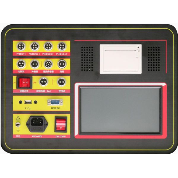
(Note: The panel colors in the figure are for reference only.)
Measures parameters including closing (opening) time, asynchronous timing, bounce time, and bounce frequency for 12 main contacts, 6 main contacts, and 6 auxiliary contacts.
This refers to the instrument's output of an adjustable DC power supply ranging from 20 to 270 V, with a default setting of 220 V, used for opening and closing operations.
This method does not utilize the instrument's internal DC power supply but instead collects the voltage signal from the circuit breaker's closing (opening) coil (either AC or DC) as the triggering input. It is primarily designed for circuit breakers with excessively high coil currents that cannot be driven by conventional instruments, such as legacy low-oil circuit breakers and single-coil permanent magnet circuit breakers.
For testing permanent magnet circuit breakers, low-oil switches, and applications without secondary control circuit diagrams.
Before conducting on-site experiments, ensure the grounding wire is properly connected.
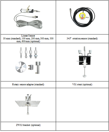
The interface for connecting linear sensors, rotary sensors, and universal sensors.
Lockout switch interface, adjustable DC 20–270V power supply, default setting: DC 220V.
Motor energy storage interface with an adjustable DC 20–270V power supply (default: DC 220V). Set the energy storage voltage output duration before operation; the range is 5–20 seconds, with a default of 8 seconds.
Print the measured data on-site.
shows parameter settings, measurements, data, etc.
During field testing, when using the instrument's internal power supply, connect the closing control line (red), opening control line (green), and common line (black) to the "internal trigger" port (aircraft plug) on the instrument panel. For the instrument's positive (+), positive (+), and negative (+) outputs, they should generally be connected before the auxiliary switch contacts to effectively protect the coil and the instrument. During wiring, ensure to disconnect the circuit breaker device's own operating power supply (by opening the switch or removing the fuse) to prevent interference between the two power sources from damaging the instrument.
Complete wiring schematic diagram of the switch tester