1206 Tape Pacakge Copper Elecment Small Quick Blow Fast Acting Surface Mount Chip Fuse
Description
12.000 Series are the fuses set the industry standard for perfor m a nce,reliability and
 quality. The solder-free design provides excellent on-off andte m p erature cycling characteristics during use and also m akes our S M Dfuses m ore heat and shock tolerant than typical sub miniature fuses.

| E1 ectrical Characteristcs | |||
| Rated Current | 1. OIn | 2.5In | 3. 5In | 
| 250mA~ 5A | 4hours, min . | 5 sec max. | - | 
| 6A~ 30A | 4hours, min . | - | 5secmax. | 
| Part No. |  			 Rated Voltage (Vdc)  |  			 			 Rated Current (A)  |  			 			 Breaking Capacity  |  			 			 Typical Cold Resistance (mOhms)2  |  			 			 Typical Voltage Drop (mV)  |  			 			 Typical Pre- Arcing I2t(A2 Sec)3  |  			Marking | |||||
| 12.000. 0. 25 | 0.25 |  			 300A@ 72/63 /32Vdc  |  			 			 300a@ 24Vdc  |  			3500 | 1400 | 0.00038 | - | |||||
| 12.000. 0. 375 | 0.375 | 1750 | 730 | 0.00077 | - | |||||||
| 12. 000. 0.5 | 0.5 | 980 | 700 | 0.0019 | - | |||||||
| 12. 000. 0.75 | 0.75 | 800 | 700 | 0.15 | - | |||||||
| 12.000. 1 | 1 | 470 | 490 | 0.18 | H | |||||||
| 12. 000. 1.5 | 1.5 | 218 | 355 | 0.4 | K | |||||||
| 12.000. 2 | 2 | 133 | 305 | 1.1 | N | |||||||
| 12. 000.2.5 | 2.5 | 79 | 240 | 1.7 | O | |||||||
| 12. 000.3 | 3 | 49 | 185 | 2.2 | P | |||||||
| 12. 000.3. 5 | 3.5 | 37 | 180 | 2.7 | R | |||||||
| 12. 000.4 | 4 | 33 | 169 | 3.2 | S | |||||||
| 12.000. 4.5 | 72 | 72 | 63 | 32 | 24 | 4.5 | 28 | 160 | 4.2 | X | ||
| 12. 000. 5 | 5 | 23 | 140 | 6 | T | |||||||
| 12. 000. 6 | 6 | 15.5 | 150 | 12 | F | |||||||
| 12. 000. 7 | 7 | 11.5 | 130 | 18 | J | |||||||
| 12. 000. 8 | 8 | 7.3 | 110 | 18 | V | |||||||
| 12. 000. 10 | 10 | 6.5 | 90 | 30 | U | |||||||
| 12. 000. 12 | 12 | 4.7 | 90 | 45 | W | |||||||
| 12. 000. 15 | 15 | 3 | 90 | 33 | Y | |||||||
| 12. 000. 20 | 20 | 2 | 90 | 80 | Q | |||||||
| 12. 000. 25 | 25 | 3 | 90 | 60 | L | |||||||
| 12. 000. 30 | 30 | 2.1 | 90 | 100 | Z | |||||||
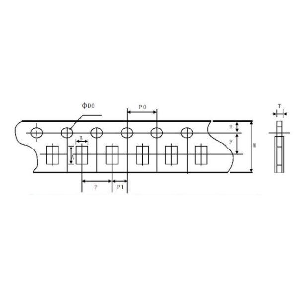
| Type | A | B | W | F | E | 
| Spec | 3.50士0. 20 | 1.90士0. 20 | 8.00士0.20 | 3. 50士0.05 | 3. 50士0.05 | 
| Type | P | P0 | P1 | DO | T | 
| Spec | 4. 00士0. 10 | 4.00士0. 10 | 2.00士0.05 | 2.00士0.05 | 0. 75土0. 10 | 

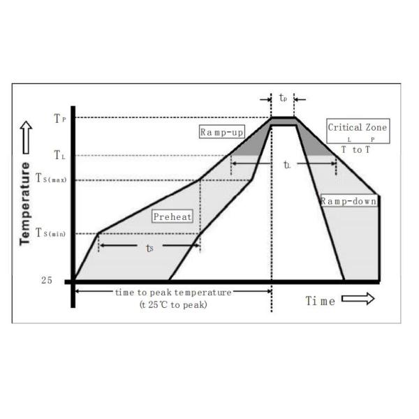
| Reflow Con diton | Pb-free asse m bly | |
| Pre Heat | -Te mperature Min (Ts(min)) | 1 50℃ | 
| = Temperature Max (Ts(max)) | 200℃ | |
| -Time_ (Minto Max) (ts) | 60一120 seconds | |
| Average Ramp-up Rate ILiquidus Te mp | 3 ℃/second max | |
| TS(max) to TL- Ramp-up Rate | 5℃/second max | |
| Reflow |  			 - Te mperature (TL) (Liquidus) 一Te mp erature (tL)  |  			 			 217℃ 60 - 150 seconds  |  		
| Peak Tem perature (TP) | I 260+0/-5℃ | |
|  			 Time within 5° C of actual peak Te mperature (tP)  |  			30 seconds | |
|  			 Ramp-down Rate Time 25° C to peak Te mperature (TP) Do not exceed  |  			 			 6° C/second max 8 minutes max 260℃  |  		|
| Wave Soldering | 260 ℃ 10 seconds max. | |

| Materials |  			 Body: Advanced Hi gh Te m perature Substrate Ter: mi natons: 100% Tin over Nickel over Copper Element Cover Coat: Confor mal C oating  |  		
|  			 Operatng Temperature  |  			 			 -55 ℃ to 125 ℃ Consult te mperature rerating curve chart.  |  		
| Thermal Shock | W ithstands 5 cyclesof-55 ℃ to 125℃ | 
| Hu mi dity | MIL-STD-202F,Method 103B, Condition D | 
| Vi braton | Per MIL-STD-202F,Method 201A | 
|  			 Insulaton Resistance (Afer Opening)  |  			Greater than 10, 000 ohms | 
|  			 Resistance to Soldering Heat  |  			MIL-STD-202G, Method 210F,Cond ition D | 

Contact Details:
Andy Wu
Email: andy@tianrui-fuse.com.cn
MP/Whatsapp: +86 13532772961
Wechat: HFeng0805
Skype: andywutechrich
QQ: 969828363