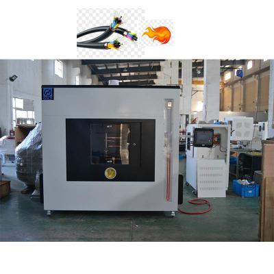
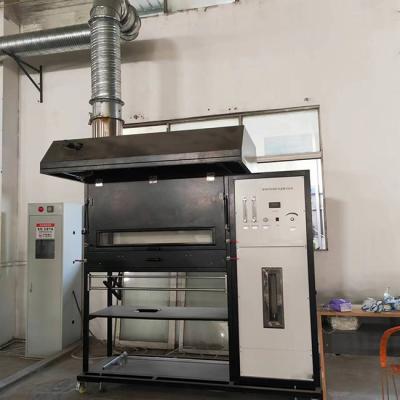
BS 476 Part 7 Flammability Testing Equipment / Surface Flame Spread Test Apparatus
Introduction:
BS 476 Part 7 specifies a method of test for measuring the lateral spread of flame along the surface of the specimen of a product oriented in the vertical position under opposed flow conditions, and a classification system based on the rate and extent of the spread of flame. It provides data suitable for comparing the end-use performances of essentially flat materials, composites, or assemblies, which are used primarily as the exposed surfaces of walls and ceilings.
Application of BS 476-7 Surface flame spread test apparatus:
Main feature:
- BS 476-7 surface flame spread test apparatus consists of a radiation panel mounted vertically in a surround and supported by a framework.
- The radiation panel is sullied with a gas-air mixture.
- The radiation panel is 850mm square for a porous refractory type burner block designed to give efficient combustion of the air-gas-air mixture, with no flaming occurring on the face of the panel under operational conditions.
- The radiation panel and its surround are supported on a framework so that the center of the panel is about 1250±100mm above floor level.
- A specimen holder and a pilot flame arrangement are mounted to one side of the apparatus.
- The specimen holder comprises a water-cooled steel frame with water-cooled face plates. The face plates overlap the specimens by 20±2mm on their top and bottom edges and over the vertical edge adjacent to the radiation panel.
- A spring-loaded clamp is positioned to clamp the specimen against the face plates.
- The portable water supply to the specimen holder ensures that the maximum temperature does not exceed 35℃ at the outlet from the specimen holder.
- The specimen holder assembly is located at 90±2° to the face of the radiation panel and in such a way that the faces of the top and bottom guides of the specimen holder are in the same plane as the inside face of the surround to the radiation panel.
- The height of the specimen holder is hinged to allow it to be swung horizontally, away from the face of the radiation panel between tests, from the test position to the standby position, and vice versa.
- The pilot burner consists of a steel tube.
- The gas and air supply lines to the radiation panel contain flow meters, pressure regulators, control valves, and safety devices.
- Heat Flux Meter: Range : 0 ~ 50 kW/m2; Surface emissivity:ɛ=0.95±0.05.
- A dummy calibration board with a holder, a calibrated heat flux meter, and mounting hardware is needed.


Specification:
Power | 220V 50 HZ |
Weight | about 400KG |
Combustion gas | propane or natural gas(Provide by Customer) |
Tool | Equipped with an air blower |