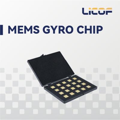
High Bandwidth 3 Axis MEMS Gyroscope Reliable MEMS Inertial Sensor For Navigation
MOQ: 1
Size: L(3.86) × W(4.48) × H(2.15) cm
Specification Number: LKF-MTG200
Product Introduction
LKF-MTG200 3-axis MEMS gyro combo is a highly reliable and cost-effective 3-axis MEMS inertial sensor designed for stable control needs. It can be widely used in navigation, control, and measurement applications, particularly for attitude stabilization. The system utilizes MEMS gyroscopes with high bandwidth, low latency, and low noise, offering excellent mechanical environment adaptability for stable control of complex products.
Technical Characteristics
Developed for Stable Control Needs
The LKF-MTG200 provides reliable performance in demanding applications with its advanced MEMS technology and robust design.
High-Precision Device Manufacturing and System Calibration Compensation Technology
Our company has developed key technologies during research and development to ensure high product performance. The system employs high-speed sampling, static error compensation (bias, scale factor, installation error across full temperature range), and dynamic error compensation to deliver optimal performance during user operation.
The LKF-MG200 3-axis MEMS gyro combo system maintains performance across wide temperature ranges and various vibration levels, providing accurate angular motion information for stabilizing and controlling servo systems with guide heads.
Table 1: LKF-MTG200 Tri-axis MEMS Gyroscope Combination Performance
| MEMS Gyro |
| Model | MTG200 |
| Range (°/s) | ±500 |
| Bias (°/h, 3σ.full temp.) | ≤30 |
| Bias stability (°/h, 10s smoothing) | ≤3 |
| Bias stability (°/h, allan) | ≤0.1 |
| Bias repeatability (°/h) | ≤1 |
| Angular random wandering(°/√h) | ≤0.1 |
| Term related to g (°/h/g) | ≤0.5 |
| Scale factor nonlinearity (ppm) | ≤100 |
| Bandwidth (Hz) | 250 |
| System |
| Power supply (V) | 5±0.2 |
| Power (W) | ≤1.5 |
| Start-up time (s) | 2 |
| Communication interface | 1 × RS-422, 1 × synchronous output, 1 × synchronous input |
| Update rate (Hz) | 2KHz |
| Dimension (mm×mm×mm) | 44.8×38.6×21.5 |
| Weight (g) | ≤50 |
| Working Environment |
| Operating temperature (℃) | -40~80 |
| Storage temperature (℃) | -55~85 |
| Vibration (g,Rms) | 7.72 |
| Shocks(g) | 1000g(1ms) |
Table 2: The Electrical Interface Of The Gyroscope
| Pin | Definition | Notes |
| 8 | POWER_IN | 5-12V power supply |
| 15 | GND | |
| 10 | RS422 R+ | RS422 interface |
| 2 | RS422 R- | |
| 9 | RS422 T+ | |
| 1 | RS422 T- | |
| 13 | GND | |
| 11 | PPS_IN | PPS signal input |
| 4 | TOV | General-purpose input/output (GPIO), 3.3V logic level, triggered on rising edge |
| 12 | GND | |
Main Features
- 100% localization of components
- In-situ replacement for STIM210
- High performance, small size
- Low weight, low power consumption
- High bandwidth, low latency
- -40℃ to +80℃ full temperature calibration compensation
- 2KHz high speed sampling
- Resistant to harsh mechanical environments
- With software online upgrade function
Applications
- Guide head stabilization
- Attitude control
- Photoelectric pods
- Servo control
- Stable platform
Figure 1: Outline Structure Dimension Diagram