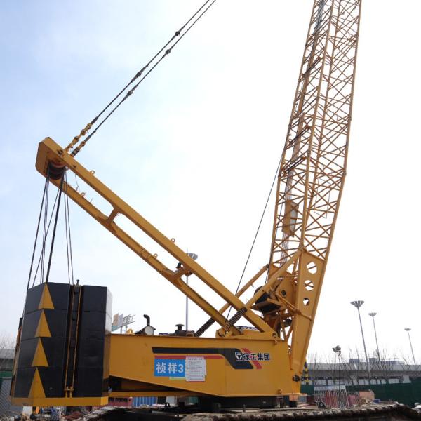
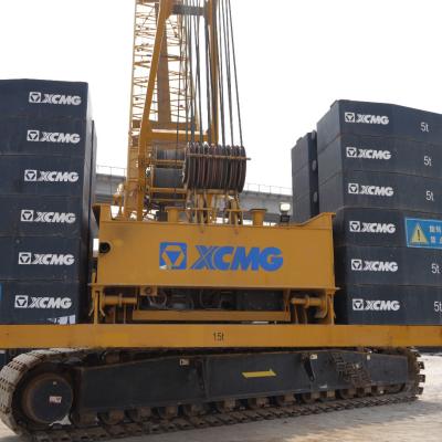
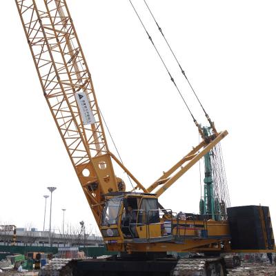
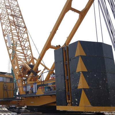
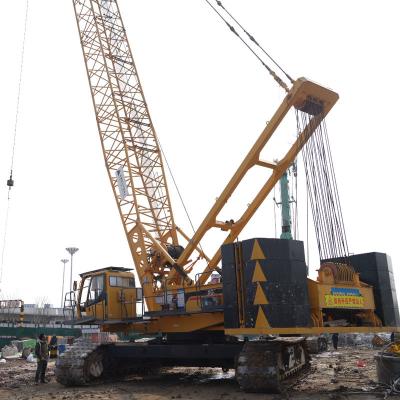
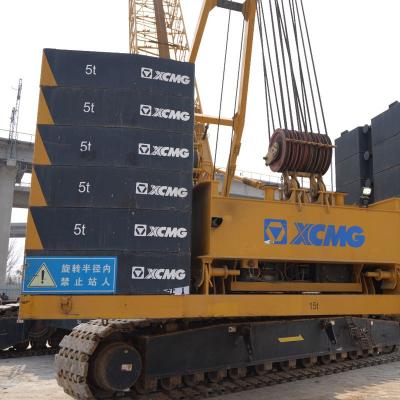
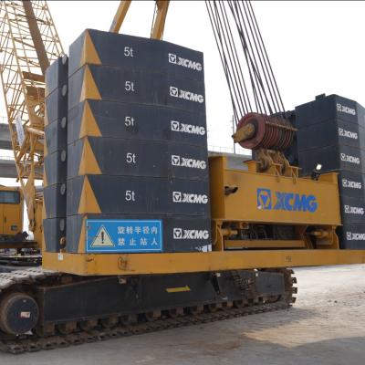
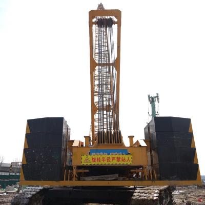
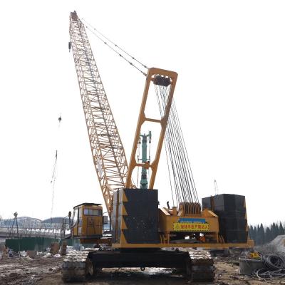
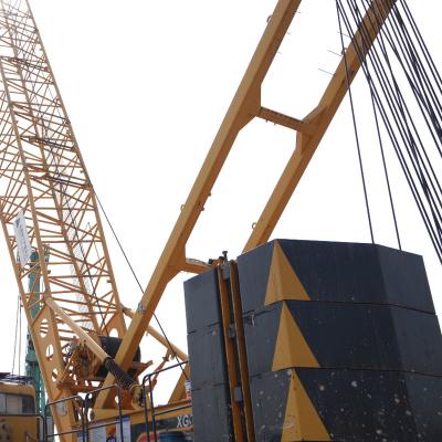
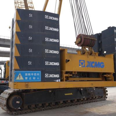
Crawler crane models: XGC 300t(-I)
Max rated lifting capacity: 300t
Maximum lifting moment: 1865t.m
Fixed jib condition
A.Fixed jib working condition_main boom section combination table
Name and quantity Main boom assembly |
Main boom bottom section 10.5m |
Main boom middle section 3m |
Main boom middle section 6m |
Main boom middle section 12mA |
Main boom middle section 12mB |
Main boom transition section 7m |
Main boom connection section1.5m |
Arm pulley block |
H(B)34 |
1 |
3[1] |
1[0] |
0[1] |
0 |
1 |
1 |
(1) |
H(B)37 |
1 |
2[0] |
0[1] |
1[1] |
0 |
1 |
1 |
(1) |
H(B)40 |
1 |
3[1] |
0[1] |
1 |
0 |
1 |
1 |
(1) |
H(B)43 |
1 |
2[0] |
1[0] |
1[2] |
0 |
1 |
1 |
(1) |
H(B)46 |
1 |
3[1] |
1[0] |
1[2] |
0 |
1 |
1 |
(1) |
H(B)49 |
1 |
2[0] |
0[1] |
2 |
0 |
1 |
1 |
(1) |
H(B)52 |
1 |
3[1] |
0[1] |
2 |
0 |
1 |
1 |
(1) |
H(B)55 |
1 |
2[0] |
1[0] |
2[3] |
0 |
1 |
1 |
(1) |
H(B)58 |
1 |
3[1] |
1[0] |
2[3] |
0 |
1 |
1 |
(1) |
H(B)61 |
1 |
2[0] |
0[1] |
3 |
0 |
1 |
1 |
(1) |
H(B)64 |
1 |
3[1] |
0[1] |
3 |
0 |
1 |
1 |
(1) |
H(B)67 |
1 |
2[0] |
1[0] |
3 |
0[1] |
1 |
1 |
(1) |
H(B)70 |
1 |
3[1] |
1[0] |
3 |
0[1] |
1 |
1 |
(1) |
H(B)73 |
1 |
2[0] |
0[1] |
3 |
1 |
1 |
1 |
(1) |
H(B)76 |
1 |
3[1] |
0[1] |
3 |
1 |
1 |
1 |
(1) |
*H(B)79 |
1 |
2[0] |
1[0] |
3 |
1[2] |
1 |
1 |
(1) |
*H(B)82 |
1 |
3[1] |
1[0] |
3 |
1[2] |
1 |
1 |
(1) |
*H(B)85 |
1 |
2[0] |
0[1] |
3 |
2 |
1 |
1 |
(1) |
Notes:
1. “*”--Indicates that the main boom combination needs to use a 1.31m waist rope; (B)--The main boom head pulley block is an option.
2. The rear pull plates of the tower boom need to be removed from each boom section, and the tower boom guide pulley needs to be removed from the main boom reducer section.
3. Two main boom intermediate sections of 3m can be used to replace one main boom intermediate section of 6m, or two main boom intermediate sections of 3m and one main boom intermediate section of 6m can be used to replace one main boom intermediate section of 12mA. When replacing, attention must be paid to the matching of the number of pull plates and pins.
B. Fixed jib working conditions Fixed jib section combination table
Name and quantity Fixed jib assembly |
Fixed jib Bottom section 4.5m |
Fixed jib middle section 3m |
Fixed jib middle section 6m |
Fixed jib top section 2.5m |
Fixed jib single pulley(S) |
F(S)7 |
1 |
0 |
0 |
1 |
(1) |
F(S)10 |
1 |
1 |
0 |
1 |
(1) |
F(S)16 |
1 |
1 |
1 |
1 |
(1) |
Notes:
1. (S) ---- indicates the optional fixed jib single pulley [the fixed jib single pulley is common to the shield arm single pulley].
2. The fixed jib boom section is common to the shield jib boom section.
3. To ensure that the arm combination function is maximized, it is recommended that users choose to purchase a fixed jib length of 7m.