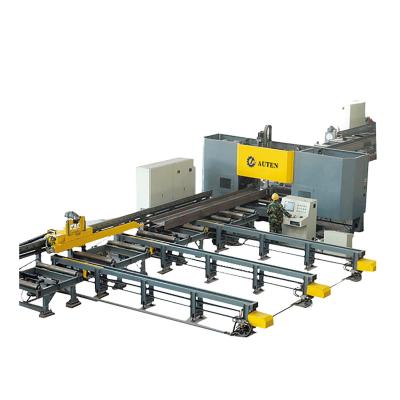
Width Range 150~1250mm CNC H Beam Drilling Marking And Tapping Machine BT40 Spindle Bore Taper
Components:
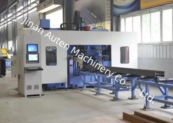
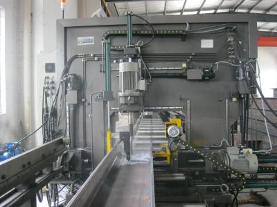
This production line is primarily composed of components including a loading horizontal material table, a 3D drilling main machine, a 3D drilling feed channel, a 3D drilling feeding device, a 3D drilling discharge channel, a cooling system, a hydraulic system, a pneumatic system, a lubrication system, an electrical system, and others.
The production line adopts a fixed bed and a movable workpiece structure, which facilitates automated production.
Main Specifications:
Parameter | Value | |
Workpiece size | Width range | 150~1250mm |
Height Range | 100~600mm | |
Length range of raw material | 2000~12000mm | |
Length range of finished workpiece | 2000~12000mm | |
Drilling spindle | Number of drilling spindles | 3 |
Spindle bore taper | BT40 | |
Spindle motor power | 11kW | |
Rotation speed | 200~3000 r/min | |
Drilling diameter range | φ5~φ30 | |
CNC axis | X-axis servo motor power | About 4.4kW |
X-axis maximum speed | 40m/min | |
Servo motor power for drilling horizontal positioning axis | About 1.5kW | |
Max. speed of drilling horizontal positioning axis | 10m/min | |
Servo motor power of drilling horizontal feed axis | About 2kW | |
Max. speed of drilling horizontal positioning axis | 10m/min | |
Drilling vertical positioning axis servo motor power | About 3kW | |
Max. speed of drilling vertical positioning axis | 10m/min | |
Drilling vertical feed axis servo motor power | About 3kW | |
Max. speed of drilling vertical feed axis | 10m/min | |
Tool magazine | Quantity | 3 sets |
Type | in-line type | |
Tool quantity | 4 x 3 | |
Hydraulic Marking unit | Qty. of characters | 36 |
Character size | Φ10 |
1. Loading Horizontal Material Table
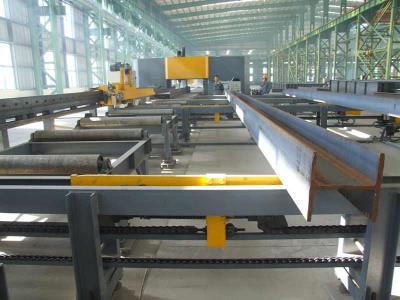
It is composed of a material table bracket, a conveyor chain, a reduction motor, and other components, serving to transport steel materials to the feed channel.
The loading horizontal material table is connected to the straightening machine procured by the customer.
2. Three-Dimensional Drilling Feed Channel
The three-dimensional drilling feed channel utilizes a power roller to connect with the on-site straightening machine of the customer, receive the straightened profiles, and automatically convey them to the clamping position of the feeding trolley. In this configuration, the height of the upper plane of the roller from the ground is 800mm; if the height of the straightening machine differs, adjustments shall be made by the user.
The feed channel is designed to carry workpieces to be processed. A photoelectric switch is installed at the front end of the channel to detect the front end of the workpiece and determine the X-direction processing reference. The side pushing device presses the workpiece tightly against the side positioning rollers, thereby achieving rough positioning of the workpiece in the Y direction.
3. Three-Dimensional Drilling Feeding Trolley
It is composed of gears, servo motors, and manipulators. The manipulator features excellent rigidity and stability, capable of automatically lifting and lowering according to profile specifications and automatically clamping workpieces. Once the manipulator clamps a workpiece, it is driven by the servo motor, and under the transmission of the gear rack, the workpiece is fed in the X direction, ensuring the longitudinal processing accuracy of drilling operations.