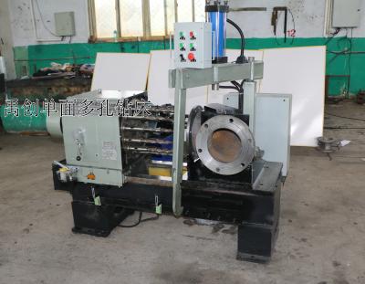
Three-sided Multi-hole Drilling Machine
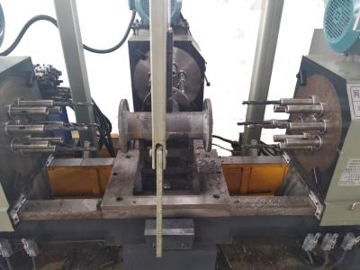
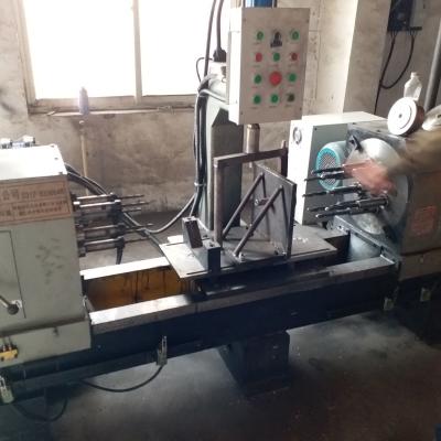
The three-sided multi-hole drilling machine can complete multi-station simultaneous processing of different types of distributed holes (regular distribution or irregular distribution) on various flanges and valve connection surfaces, which can improve processing efficiency and reduce the number of clamping and positioning times.
Main features
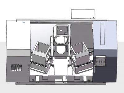
1. This machine can process any valve body with three flange faces on the same axis, or any side can be processed separately;
2. High processing efficiency: During the processing, the machine uses the power head to work simultaneously to complete the drilling process of multiple holes on the flange at the same time, with a beat of less than 2 minutes;
3. Reduce labor: Traditional drilling processing requires the mold to be processed one hole at a time, which wastes time. This machine can process multiple holes on three flange faces at the same time, and one employee can operate multiple machines at the same time, thereby improving efficiency;
4. High uniformity of processing size: This special machine is all controlled by PLC system, one-to-one tooling positioning, only one adjustment is required, and the drilling work can be easily completed by simply installing the workpiece later;
5. Easy to operate: This machine can be learned and mastered by anyone with no processing experience.
Main components
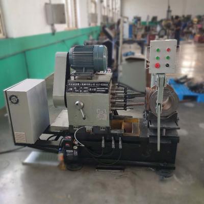
This machine tool is mainly composed of a bed, a gear box, a power head and a lubrication system.
Application
The three-sided multi-hole drilling machine is suitable for various valve fittings such as gate valves and water conservancy valves: this machine can process any three flange faces on the same axis of the valve body, and can also process any side separately.
Specifications
Project | Machine Specifications | YC lll Z200HT | YCIll Z400HT | YC lll Z600HT | YCllI Z800HT |
Technical specifications | Maximum drilling center distance (mm) | φ295 | φ525 | φ770 | φ950 |
Maximum processing length (mm) | 600 | 800 | 1000 | 1100 | |
Minimum processing length (mm) | 200 | 300 | 300 | 400 | |
Maximum processing dimension from intermediate flange to center (mm) | 400 | 600 | 700 | 900 | |
Minimum processing size from intermediate flange to center (mm) | 150 | 200 | 200 | 250 | |
Travel (mm) | 280 | 395 | 450 | 450 | |
Drill bit connection method (Morse taper shank) | Moshi 2# 莫式2# | Moshi 2#/ Moshi 3# 莫式2#/莫式3# | Moshi 2#/ Moshi 3# 莫式2#/莫式3# | Moshi 3#/ Moshi 4# 莫式3#/莫式4# | |
Machining precision | Position (mm) | ≤0.5 | ≤0.8 | ≤1 | ≤1 |
Surface roughness | 12.5 | 12.5 | 12.5 | 12.5 | |
Spindle drive | Transmission form (gear speed change) | Second gear speed change | Second gear speed change | ||
Spindle speed range (r/min) | 225/286 | 159/231 | |||
Spindle motor model | YE2-132M-6-5.5KW | YE2-132M-6-7.5KW | 11KW reduction motor | 11KW reduction motor | |
Numerical control system | PLC | ||||
Feeding form | Hydraulic transmission | ||||
Machine tool appearance | Overall dimensions of the machine tool (length x width and height mm) | 2800X1600X1500 | 3200X2000X1700 | 3400X2200X2000 | 3500X2600X2200 |
Machine tool weight(kg) | 2000 | 3000 | 4200 | 5000 |
Processed products