Specifications
Model Number :
F4BTMS265
MOQ :
1PCS
Delivery Time :
2-10 working days
Payment Terms :
T/T, Paypal
Price :
0.99-99USD/PCS
Certification :
ISO9001
Supply Ability :
50000pcs
Brand Name :
Wangling
Place of Origin :
China
Packaging Details :
Packing
Description

Introduction

In the demanding world of aerospace, defense, and high-frequency communications, material performance and reliability are paramount. F4BTMS265 from Taizhou Wangling Insulation Material Factory represents a significant advancement in PTFE-based composite technology. As part of the F4BTMS series—the upgraded successor to the F4BTM family—this material combines the benefits of ultra-thin, ultra-fine glass fiber reinforcement with high ceramic filling to deliver exceptional electrical, thermal, and mechanical performance.

F4BTMS265 offers a dielectric constant of 2.65 with ultra-low dissipation factor, making it ideal for phase-sensitive applications, microwave circuits, and aerospace systems where signal integrity and dimensional stability are critical. Its unique construction minimizes the "fiberglass effect" on electromagnetic wave propagation while maintaining excellent dimensional stability—a balance that traditional woven fiberglass PTFE materials struggle to achieve.

This article provides a comprehensive overview of F4BTMS265 laminate properties, a detailed 2-layer PCB design example, and key sourcing information for engineers and procurement professionals.

What Is F4BTMS265 and What Are Its Dk, Df, CTE, and Aerospace PCB Specifications?

What Is F4BTMS265 Laminate?

F4BTMS265 is a high-performance PTFE (polytetrafluoroethylene) composite substrate from the F4BTMS series manufactured by Taizhou Wangling Insulation Material Factory. The material represents a technological breakthrough over the previous F4BTM series, featuring an advanced formulation that combines:

Ultra-thin, ultra-fine glass fiber cloth – Minimal reinforcement that reduces the "fiberglass effect"

High ceramic filling – Large amounts of uniformly distributed specialty nano-ceramics mixed with PTFE resin

Optimized processing – Proprietary manufacturing techniques for superior consistency

Key Differentiator: Minimized Fiberglass Effect with Enhanced Stability

Unlike traditional woven fiberglass PTFE materials, F4BTMS265 uses ultra-thin, ultra-fine glass fiber cloth as reinforcement. This unique approach:

Minimizes the "fiberglass effect" – Reduces dielectric anisotropy and non-uniformity during electromagnetic wave propagation

Lowers dielectric loss – Achieves ultra-low dissipation factor compared to conventional woven glass PTFE

Enhances dimensional stability – Maintains excellent mechanical stability despite minimal glass content

Reduces X/Y/Z anisotropy – More isotropic electrical properties than traditional woven glass materials

Increases usable frequency – Stable performance to 40 GHz and beyond

Aerospace-Grade Reliability

F4BTMS265 is designed for the most demanding aerospace and defense applications, featuring:

Excellent radiation resistance – Stable electrical and physical properties after irradiation exposure

Low outgassing – Meets vacuum outgassing requirements for space applications

Wide operating temperature range – -55°C to +260°C

Low moisture absorption – 0.025% for stable performance in humid environments

Properties of F4BTMS265 Laminate

Property Test Condition Units Typical Value
Electrical Properties
Dielectric Constant (Typical) 10 GHz 2.65
Dielectric Constant (Design) 10 GHz 2.65
Dielectric Constant Tolerance ±0.04
Dissipation Factor 10 GHz 0.0012
20 GHz 0.0014
40 GHz 0.0018
Temperature Coefficient of Dk (TCDk) -55°C to 150°C ppm/°C -88
Peel Strength (1 oz RTF Copper) N/mm >1.8
Volume Resistivity Normal MΩ·cm ≥1 × 10⁸
Surface Resistivity Normal ≥1 × 10⁸
Electrical Strength (Z-direction) kV/mm >34
Breakdown Voltage (XY-direction) kV >42
Thermal Properties
CTE (X-axis) -55°C to 288°C ppm/°C 15
CTE (Y-axis) -55°C to 288°C ppm/°C 20
CTE (Z-axis) -55°C to 288°C ppm/°C 72
Thermal Stress 260°C, 10s, 3 cycles No delamination
Thermal Conductivity Z-direction W/(m·K) 0.36
Long-Term Operating Temperature °C -55 to +260
Mechanical & Physical Properties
Moisture Absorption 20±2°C, 24 hours % 0.025
Density Room temperature g/cm³ 2.26
Flammability UL-94 V-0
Material Composition PTFE + Ultra-thin glass fiber + Ceramic

Ultra-Low Loss Across Frequency

F4BTMS265 demonstrates exceptional low-loss performance across a wide frequency range:

Frequency Dissipation Factor
10 GHz 0.0012
20 GHz 0.0014
40 GHz 0.0018

This ultra-low loss characteristic makes F4BTMS265 ideal for phase-sensitive applications where signal integrity must be maintained over long transmission paths.

Excellent Frequency Stability (Up to 40 GHz)

F4BTMS265 maintains stable dielectric constant and low loss values up to 40 GHz, making it suitable for:

Phase-sensitive antennas – Stable phase performance across frequency

Microwave circuits – Consistent impedance and signal integrity

Radar systems – Reliable performance in demanding applications

Temperature Stability

With a TCDk of -88 ppm/°C from -55°C to 150°C, F4BTMS265 offers:

Stable phase performance – Minimal dielectric constant variation across temperature

Reliable operation – Consistent electrical performance in extreme environments

Wide operating range – -55°C to +260°C long-term use

Low CTE for Dimensional Stability

F4BTMS265's CTE values (15/20/72 ppm/°C in X/Y/Z) provide:

Excellent dimensional stability – Critical for multi-layer and high-density designs

Reliable PTHs – Reduced thermal stress on plated-through-holes

Consistent registration – Maintains alignment across temperature cycles

Features and Benefits Summary

Feature Benefit
Ultra-thin, ultra-fine glass fiber reinforcement Minimized "fiberglass effect"; reduced anisotropy; lower dielectric loss
High ceramic filling Enhanced dimensional stability; improved thermal and mechanical properties
Dk of 2.65 ± 0.04 Tight tolerance; excellent lot-to-lot consistency
Ultra-low Df (0.0012 @ 10 GHz) Excellent signal integrity; low transmission loss
Stable performance to 40 GHz Suitable for microwave, radar, and phase-sensitive applications
TCDk of -88 ppm/°C Temperature-stable dielectric constant; reliable phase performance
CTE of 15/20/72 ppm/°C Excellent dimensional stability; reliable PTHs
Radiation resistance Stable performance after irradiation exposure; space-qualified
Low outgassing Meets vacuum outgassing requirements for space applications
Low moisture absorption (0.025%) Stable performance in humid environments
Long-term operating temperature (-55°C to +260°C) Suitable for extreme environments
UL 94 V-0 flammability Safety certified for critical applications
RTF low-roughness copper foil (standard) Reduced conductor loss; excellent peel strength (>1.8 N/mm)
Standard PTFE processing Compatible with standard PTFE PCB fabrication techniques

Standard Offerings

F4BTMS265 and the F4BTMS series are available in a wide range of thicknesses, panel sizes, and copper cladding options.

Thickness (mm) Thickness (mil) Tolerance (mm) Tolerance (mil)
0.127 5 ±0.0127 ±0.5
0.254 10 ±0.02 ±1.0
0.508 20 ±0.03 ±1.19
0.635 25 ±0.04 ±1.58
0.762 30 ±0.04 ±1.58
0.787 30.1 ±0.04 ±1.58
1.016 40 ±0.05 ±2.0
1.27 50 ±0.05 ±2.0
1.5 59 ±0.06 ±2.5
1.524 60 ±0.06 ±2.5
1.575 62 ±0.06 ±2.5
2.03 80 ±0.08 ±3.2
2.54 100 ±0.10 ±4.0
3.175 125 ±0.13 ±5.0
4.06 160 ±0.18 ±7.0
5.08 200 ±0.20 ±8.0
6.35 250 ±0.25 ±10.0

Note: Minimum thickness is 0.127mm. Additional thicknesses available in 0.127mm increments. Custom thicknesses available upon request.

Standard Panel Sizes & Copper Claddings

Parameter Options
Standard Panel Sizes 305 × 460 mm (12" × 18")
460 × 610 mm (18" × 24")
610 × 920 mm (24" × 36")
Custom sizes available
Copper Thickness 0.5 oz (18 μm)
1.0 oz (35 μm)
Other thicknesses available upon request
Copper Foil Types RTF – Low-roughness copper (standard)
50Ω Embedded Resistor Copper Foil (NiP alloy, 0.2μm thickness, 50±5Ω/sq)
Copper-clad or aluminum-clad versions available

Metal-Backed Options (F4BTMS265-AL / F4BTMS265-CU)

F4BTMS series also offers metal-backed versions for shielding or heat dissipation applications:

Model Metal Base Density (g/cm³) Thermal Conductivity (W/m·K) CTE (ppm/°C) Available Metal Thickness (mm) Panel Size (mm)
F4BTMS265-CU Copper 8.9 380 17 0.48, 0.98, 1.48, 1.98, 2.98, 3.98 460 × 610
F4BTMS265-AL Aluminum 2.7 180 24 460 × 305

Note: Metal thickness tolerance: +0.02 / -0.05 mm. Custom thicknesses available upon request.

F4BTMS265-AL = F4BTMS265 with aluminum backing
F4BTMS265-CU = F4BTMS265 with copper backing

2-Layer PCB Design Example Using F4BTMS265

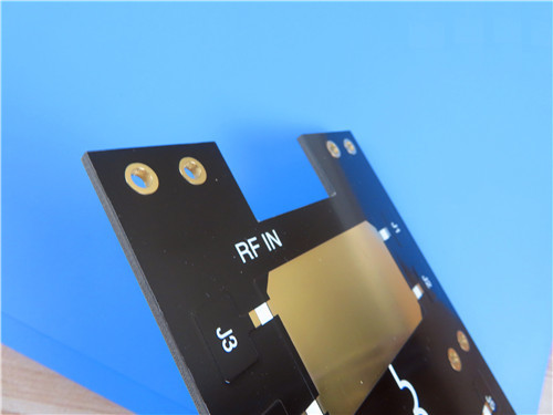
To demonstrate the practical application of F4BTMS265, the following is a complete 2-layer rigid PCB design case.

What Is F4BTMS265 and What Are Its Dk, Df, CTE, and Aerospace PCB Specifications?

PCB Design Specifications

Parameter Specification
Base Material F4BTMS265 (Taizhou Wangling)
Layer Count 2-layer rigid
Board Dimensions 97.00 mm × 76.00 mm per panel, ±0.15 mm
Minimum Trace/Space 14 / 14 mils
Minimum Hole Size 0.25 mm
Blind/Buried Vias None
Finished Cu Weight 1 oz (35 μm) all layers
Via Plating Thickness 20 μm
Surface Finish ENIG (Electroless Nickel Immersion Gold)
Top Silkscreen White
Bottom Silkscreen None
Top Solder Mask Black
Bottom Solder Mask None
Electrical Testing 100% prior to shipment
Artwork Format Gerber RS-274-X
Accepted Standard IPC-Class-2
Service Area Worldwide

Design Observations

This board (97 mm × 76 mm) features a significant component count (39 components) with only 2 nets, suggesting a complex RF or microwave functional module. Key observations include:

30 mil (0.762 mm) dielectric thickness – Standard thickness for high-frequency PCB designs

Black solder mask on top layer – Provides protection and aesthetic consistency; black solder mask is often preferred for high-frequency applications due to its matte finish and reduced reflectivity

White silkscreen on top layer – Clear component marking against black solder mask; improves assembly and inspection

ENIG surface finish – Provides excellent solderability and flatness for RF connections

Generous trace/spacing (14/14 mils) – Suggests the design may involve higher voltage or power considerations, or may simply be a less densely populated RF design

High via count (25 vias) – Reflects the need for frequent grounding or shielding in a microwave design

F4BTMS265's low loss (Df ≈ 0.0012 @ 10 GHz) – Critical for maintaining signal integrity at high frequencies

IPC-Class-2 compliance – Ensures reliability for commercial aerospace and defense applications

Manufacturing Process Highlights

Standard PTFE processing – F4BTMS265 can be fabricated using standard PTFE PCB techniques

Excellent dimensional stability – Ultra-thin glass fiber reinforcement minimizes distortion during processing

Dense-hole capability – Supports 0.25 mm minimum hole size

Multi-layer capability – Suitable for multi-layer and backplane applications

100% electrical testing – Guarantees functional integrity of every board

Typical Applications

- Aerospace equipment, space and cabin equipment
- Microwave, RF
- Radar, radar
- Feed networks
- Phase-sensitive antennas, phased array antennas
- Satellite communications, and more

Conclusion

F4BTMS265 from Taizhou Wangling Insulation Material Factory represents a significant advancement in PTFE-based composite technology, combining the benefits of ultra-thin, ultra-fine glass fiber reinforcement, high ceramic filling, and aerospace-grade reliability. With a dielectric constant of 2.65 ± 0.04, dissipation factor of 0.0012 at 10 GHz, and stable performance up to 40 GHz, F4BTMS265 delivers the performance required for the most demanding microwave, radar, and aerospace applications.

Key advantages include:

Aerospace-grade reliability – Radiation resistant, low outgassing, space-qualified

Ultra-low loss (Df = 0.0012 @ 10 GHz) – Excellent signal integrity for phase-sensitive applications

Ultra-thin glass reinforcement – Minimized "fiberglass effect"; reduced anisotropy

40 GHz capability – Suitable for microwave and radar applications

Excellent temperature stability – TCDk of -88 ppm/°C from -55°C to 150°C

Low CTE (15/20/72 ppm/°C) – Excellent dimensional stability; reliable PTHs

Low moisture absorption (0.025%) – Stable performance in all environments

Cost-effective alternative – Replaces similar Western materials with competitive pricing

Standard PTFE processing – Compatible with standard fabrication techniques

Whether used in spacecraft electronics, radar, or phase-sensitive antenna systems, F4BTMS265 provides a reliable, high-performance foundation for demanding high-frequency circuit designs.

Send your message to this supplier
Send Now

What Is F4BTMS265 and What Are Its Dk, Df, CTE, and Aerospace PCB Specifications?

Ask Latest Price
Model Number :
F4BTMS265
MOQ :
1PCS
Delivery Time :
2-10 working days
Payment Terms :
T/T, Paypal
Price :
0.99-99USD/PCS
Certification :
ISO9001
Contact Supplier
What Is F4BTMS265 and What Are Its Dk, Df, CTE, and Aerospace PCB Specifications?

Shenzhen Bicheng Electronics Technology Co., Ltd

Site Member
11 Years
guangdong, shenzhen
Since 2003
Business Type :
Manufacturer, Distributor/Wholesaler, Exporter, Seller
Total Annual :
10 million-18 million
Employee Number :
350~450
Certification Level :
Site Member
Contact Supplier
Submit Requirement